

RHINO MkII INTERIOR LIGHTING By Simon Larsen |

VEHICLES & WARMACHINES |
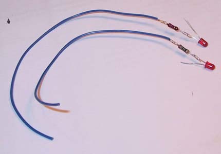
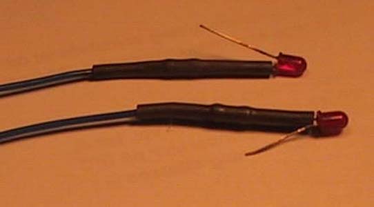
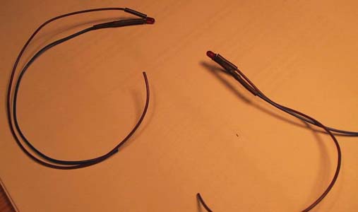
Step 2.3: Mounting resistors and wires to the LED's. Trim the component-legs on the resistors, to a minimum (about 5mm is usually enough). Trim the component-legs on the LED's, but keep the proportions between the short and the long leg! For instance, trim one to about 8 or 9mm, and the other to 14 or 15mm. Solder the resistor to the short leg on the LED. Take a strip of wire, about 15cm long. Remove the insulation from one of the tips, about 5mm will do. Solder the strip of wire to the other leg on the resistor. Cut a fitting length of shrinkage tubing, and pull it over the end of the wires, so it covers the legs on both the resistor, and the LED leg that it's connected to. Heat the shrinkage tubing, using a lighter or a heat-gun, until it's fully contracted. Attach another length of wire, about 15-17cm in length, to the other leg of the LED. Preferably this is of another colour. Fit a small length of shrinkage tubing to the joint between LED and wire. Heat up. Repeat for the other side. |


">

">
">
">
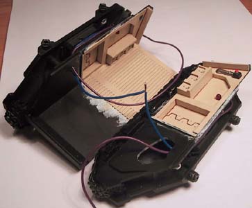
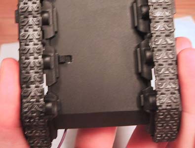
Chapter 3: Assembly Step 3.1: Fitting the LED's. First off, dry-fit the LED's into the holes in the sides. If you want, using a fine pen, you can 'draw' protective bars onto the LED. It looks pretty good once they're switched on. This is how they should look (Don't worry about the wires I've soldered together at the centre). Note that I have drilled two small holes (about 2 - 2.5mm in diameter) on the right-hand side track, and led the wires through there. Once you are happy with the fit of the LED's, give them a drop of superglue on the back, inside the |
Figure 6 |
Figure 7 |


">
">
">
">
Step 3.2: Modifying and fitting the switch. I am assuming you have managed to scrounge a switch somewhat similar to mine. It should initially have three pins (legs), and the lever should have two positions. |
">
">
">
">
">
">
">
">
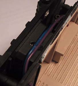
track-assembly. After the initial glue has dried, glue the wires to the top of the door-frames, again using superglue. |
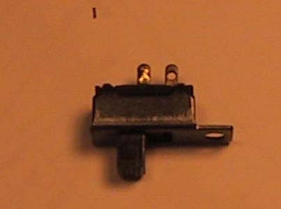
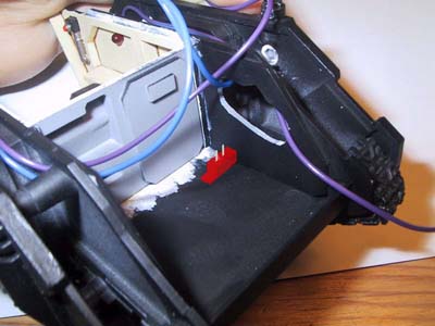
Modify it so it resembles this. Yes, that means cutting off some stuff: The metal edge on one side, and the pin on the same side! Now go and fetch the middle bulkhead for the Rhino and affix it (I recommend a dry-fit for now), and use it as a guide as to where to put the switch. Here's the idea. |
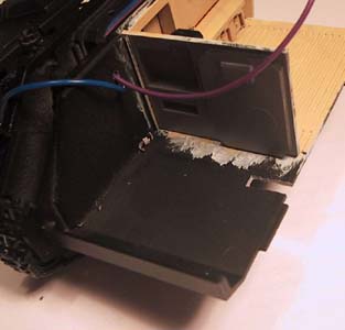
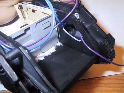
Now, as you might have noticed, in order to make this thing work, you need to cut a hole in the floor-section of the Rhino. Here we go. Now, as you will notice in this (very grainy, sorry) picture. |